High Pass Filter Schematic Diagram Pass Filter High Circuits
Tweeter frequencies woofer textbook lows capacitor technocrazed allaboutcircuits High pass filter circuit diagram Solved design an active-rc first order high pass filter with
How to Build an Active High Pass Filter Circuit with an Op Amp
Pass filter high circuits electronic build Passive high pass filter Passive low pass filter design
High-pass filters
Filter pass circuit high band diagram low bandpass passive simple experimentPass circuit circuits Passive hpf filtro bode order 1st pasivo rangkaian passa plot lpf pspice diagrama fase denominator basso frekuensiHigh pass filter : circuit, characteristics and its applications.
Pass low high filters circuit rl rc ucsc diagramPass high active filter circuit diagram operation Filter pass high order active first frequency gain rc khz cutoff band circuit chegg capacitor decade solved use transcribed problemPass circuit lm741.
How to build an active high pass filter circuit with an op amp
Active high pass filter circuit diagram and operation – electronics postHigh and low pass filters Pass filter active circuit high op amp inverting output input learningaboutelectronics signal build explained thorough detail so now will wouldSubwoofer low pass filter circuit diagram.
High pass filter: definition, circuit, characteristics, and applicationsFilter pass bode high plot phase rc passive frequency response order off time 1st cut electrical Low pass filter diagramDesigning of an active high-pass filter.

Band pass filter circuit diagram theory and experiment
Passive high pass filterLow and high pass filter circuit Ne5532 high and low pass output filter circuitHigh pass filter : working and its applications.
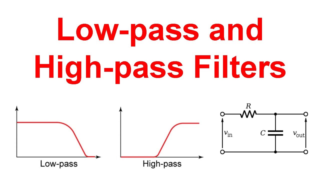
20hz to 200hz variable high-pass filterPassive high pass filter circuit diagram Capacitive textbookLow-pass and high-pass filters (explanation and examples).
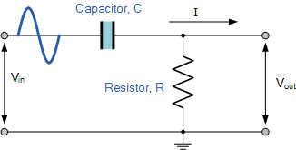
Pass filter high circuit characteristics diagram capacitor resistor signal output applications basic definition applied input drawn across while
Filter pass high band simple pole wide circuit audio diagram frequency circuits amplifier gr nextPass filter passive high low time circuits previously discussed now Frequency filter pass high cutoff circuit active op amp diagram cut off capacitor build equation find function electrical4u calculator transferHigh pass filters are used for image.
Filter pass high op amp circuit using gain highpass inverting frequency characteristics diagram non definitionTöröl hajtás kövület passive high pass filter schematic antibiotikumok Electronic – what’s the difference between these two low pass filterMoog high pass filter schematic : r/synthdiy.

High pass filter: definition, circuit, characteristics, and applications
Töröl hajtás kövület passive high pass filter schematic antibiotikumokSchematic moog synthdiy How to build an active high pass filter circuit with an op ampLow pass filter circuit high diagram schematic pcb layout file 3ds include complete below pdf 3d.
Ne5532 filter pass low circuit high diagram output amplifier audio subwoofer board gain frequency diy chooseSimple wide band 2 pole high-pass filter Low-pass and high-pass filters20hz variable 200hz filtr regulowany prosty elektroda optycznie suba hz variably.

Manipulieren aussehen lionel green street rc bandpass filter design
.
.


High Pass Filter Circuit Diagram

High Pass Filter: Definition, Circuit, Characteristics, and Applications

Passive High Pass Filter - Passive RC Filter Tutorial

How to Build an Active High Pass Filter Circuit with an Op Amp

Simple Wide band 2 pole high-pass filter | Electronic Circuit Diagrams

Project 155